You may have heard of rectifiers before. From charging our cell phones to powering large industrial processes, there are many types of rectifiers used in a variety of applications. While commonly used for DC motors, SCR control technology can be found anywhere from steel mills to power plants.

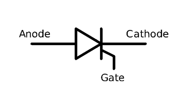
Basic Diagram of a Silicon Controlled Rectifier
Many industrial and automation professionals understand the basic context for SCR-appropriate automation solutions. However, the silicon controlled rectifier (SCR) is often misunderstood. This article will explore the principles behind SCR control and review the best ways to test this technology.
Gate Leads and Triggers
An SCR converts an AC voltage to a DC voltage. Unlike a diode that turns on when .7V travels across the anode and cathode, an SCR includes a gate lead that requires a trigger to activate the on-state condition. This allows a variable DC voltage to be produced from an SCR because it can be triggered at different points in a sine wave.
Two critical values related to triggering are the gate trigger voltage VGT and the gate trigger current IGT. These values are usually listed on a datasheet as the maximum allowable values. It takes at least .7 volts applied to the gate lead to trigger an SCR. Once activated, it will remain on until the gate trigger voltage is removed or the anode to cathode current (also known as holding current IH) is reduced to a level below its designed operating threshold.
Blocking Voltages
Another important parameter to consider in SCR control is the blocking voltage. Two values on a datasheet relate to this: peak repetitive off state forward voltage VDRM and peak repetitive off state reverse voltage VRRM.
These values are critical because it determines how much voltage an SCR can effectively block in forward and reverse while in an off-state condition without breaking over. Exceeding this value will damage the device. The devices are not perfect open and closed switches, and will allow a certain amount of leakage current at VDRM and VRRM. The maximum values for this are listed on a datasheet as peak off-state current IDRM and peak reverse current IRRM.
Blocking voltages vary for different applications, but power SCR’s in DC drives typically range from approximately 1400V to 2200V.
Critical Rate of Rise
And finally, one last parameter to consider with an SCR is the critical rate of rise of off-state voltage. The critical rate of rise determines how many volts in a given amount of time an SCR can block typically given in V/µs. If an SCR is put into an application where the rate of rise is greater than the value listed on its datasheet, the device can break down and turn on when not triggered. This can destroy an SCR if consideration is not given to this. To slow the rate of rise, a resistor/capacitor circuit is placed in parallel with an SCR.
How do you test SCR's?
There are a few basic methods that can determine if a device is bad:
Make sure that power is removed from the device before attempting any of these tests!
- Measure the resistance of the gate and cathode lead. Typical values are anywhere from 8Ω to 40Ω. If values in the MΩ range are observed, the gate lead is open and the device is defective.
- Place a meter across the anode and cathode to measure the resistance. Reverse the leads and measure the resistance again. Typical values should be in the 400kΩ all the way into the MΩ range in both directions.
- Put a FLUKE or other type of meter into a diode test mode. Place the positive lead on the anode and the negative on the cathode. Using a low voltage DC source such as a 9V battery, place the positive lead on the gate and the negative lead on the cathode. (Do not hold this DC source on the gate cathode for long periods of time without a resistor in series with it or damage may occur to the device.) The SCR will turn on and the meter should read like a typical diode. Depending on the type of SCR, the meter usually does not produce enough current to keep the SCR on so removing the DC source from the gate lead will shut it off.
Professionally Tested and Optimized SCR's
The SCR is a simple device that is often misunderstood. A basic understanding of its construction and some simple testing can usually identify a defective device. More in-depth testing of VGT, IGT, VDRM and VRRM can be conducted for a comprehensive evaluation. Premier Automation can offer basic and advanced testing as needed in our fully-equipped 40,000 ft facility.
Our engineers are experts in drive and automation solutions, specializing in a broad portfolio of industries and applications. We do electrical control system design, retrofits, upgrades, and repairs, custom panel building, power and distribution, nationally ranked control system integration, and more. Premier Automation delivers innovative answers for any automation challenge.
If you're seeking a true electrical control partner, please contact us today. We are happy to help!


